Cellular IoT Development

Cellular IoT Development

Cellular IoT is what some might call the new kid on the block – in some ways it is; on the other hand it is based on an existing infrastructure – cellular networks, which is used on every mobile phone in the world. Cellular IoT is rapidly developing, and will eventually become the driving component of many businesses. If you’d like to get a better overview of cellular IoT, I’d recommend this article –https://www.iotforall.com/what-is-cellular-iot.

In this article, we’ll take a quick look at developing cellular IoT devices, and some of the major things to keep in mind during development.

To begin with, it is critical that you have a solid understanding of the hardware before diving into the firmware. As with any hardware/firmware engineering project, picking components is one of the first steps.

To keep things fairly simple, let’s consider an IoT device, which uses a cellular modem for communications, has one or more sensors, and is battery powered. The hardware setup for this IoT device could look like this:
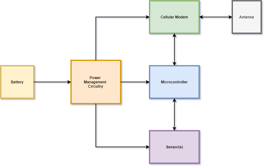
Here you have the core components:

  • A battery
  • A microcontroller (typically low power)
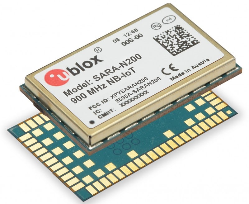
  • A cellular modem (and antenna)
  • One or more sensors, depending on your application/use case
  • Power circuitry

So far, I find the cellular modem to be the most complex component – mainly because it’s a self contained system which we have virtually no control over. To develop the firmware for a cellular IoT device, here are a few key points to keep in mind:

Power Management

Most cellular modems have a defined power up sequence, and you need to keep this in mind when writing initialization code. Refer to the datasheet of your chosen modem to get the exact details. Moreover, power management needs to be a key consideration in your design especially since the cellular modem is typically the most power-hungry component. In your hardware design, be sure to accommodate peak current of up to 2 Amps, to be on a safe side.

Depending on your application requirements, your IoT device may be required to be powered on at all times, but then only send data at specified intervals. One possible power management scenario could be:

  • The microcontroller is always powered on, but is in low power mode – check your microcontroller documentation/settings for how to configure these low power modes.
  • The sensors are usually powered off, until they are ready to be used. This is determined and controlled by the application.
  • The cellular modem is usually powered off until data is ready to be transmitted or received.

In this scenario, your hardware design needs to accommodate a seamless power on/off mechanism for each of the components. Doing so goes a long way in minimizing power consumption – a key consideration in battery powered IoT devices.

Looking specifically at the modem, you can apply one or more of the following power management options:


  • Use AT commands to put the modem in some kind of low power mode, if supported.
  • Use Power Saving Mode (PSM) or eDRX (Extended Discontinuous Reception) functionality provided by the modem, if supported. Tread carefully here, as these features may depend on cellular operators may cause more problems than they solve if not properly configured.
  • Completely cut off power to the modem when it is not needed. This is achieved typically though a combination of hardware and firmware. What’s extremely important here is to ensure that you gracefully shut down the modem (typically via AT commands) before completely cutting off power. Abrupt shutdowns of the modem tends to cause a lot of problems, such as potentially corrupting the modem firmware, or being denied from connecting to a cellular network because it did not “gracefully” disconnect, or some other weird reasons. Either way, the point here is to ensure that the modem shutdown sequence is graceful. The documentation will often describe how to do a shutdown sequence properly.

Core Modem (and IoT device) Functionality

Functionally speaking, cellular modems in IoT device serve one primary purpose: sending and receiving data remotely. To do this, the application firmware typically needs to implement, as a bare minimum, the following:

  • Initialization – turn on the modem and gracefully shut it down, as well as initializing the AT/UART interface,
  • Network functionality – setting up and tearing down a cellular network connection,
  • Establishing a PDP context – which in (oversimplified) terms, is essentially connecting to the internet and receiving an IP address,
  • Server functionality – setting up and tearing down a connection to a remote host/server. This is where the IoT device “dumps” data to,
  • Data transmission/reception – the actual sending and receiving of data. How this is done depends on what protocol is being used (raw TCP, HTTP, MQTT, etc).

Therefore, to implement the above-mentioned features in firmware, one way to go about it is to develop the following modules:

  • An AT interface – built on top your UART driver, this will be responsible for sending AT commands and receiving the raw responses,
  • An AT response parser – all AT commands return responses in various formats. You need to develop a parser to be able to extract the necessary information,

Using these two modules as a base, you could then implement “higher level” modules for:

  • “Device level” functionality – for stuff like reading modem information and configuring it.
  • “Network level” functionality – for setup network connectivity parameters, reading network connectivity data, setting up/tearing down network connection, etc. This module could also be used to implement setup and teardown of PDP context.
  • “Server level” functionality – for setup and teardown of remote server connection, TLS connection, sending/receiving device data, etc.

On a final note, you also need to consider to implement the ability to perform an upgrade of the modem firmware. This is extremely important, as this firmware essentially dictates how the modem works and communicates with the cellular network. For certain certifications, this is even a major requirement.

Conclusion

Developing cellular IoT devices is a challenging endeavour, and there are a lot of key considerations to be kept in mind when designing such a device. These considerations include, but are not limited to:

  • Modem selection – you want to pick modems that support the protocols and network technologies (LTE CAT-M1, NB-IoT, etc) needed for your product.
  • Efficient power management (which needs to be implemented both in hardware and software).
  • Ability to upgrade modem firmware
  • Developing modem “drivers”, and your final application. Write your modem drivers and abstract as much as possible, which will make it easy to switch modems when/if necessary.
Fast Tracking BLE Development With BleuIO

Fast Tracking BLE Development With BleuIO

Overview

I recently started working on a new project that involves BLE (Bluetooth Low Energy). I quickly realized I need a fast way of validating/testing connectivity between two BLE devices. Specifically, my application required a BLE connection between my PC and a test device – and like any modern 21st century human, I googled it.  Luckily I stumbled upon a solution that was definitely worth sharing, hence this blog.

Introducing.. the BleuIO Dongle from Smart Sensor Devices AB, a company based in Sweden specializing in smart sensors and devices. Check out their Youtube channel here.

This is a pretty sweet solution that could really help you speed up your BLE application development – suffice it to say that it was definitely made for developers. There is a nice library of scripts, tutorials and utilities to really help you hit the ground running. I definitely had a plug and play experience, which is something I truly appreciate as a developer.

They’ve made some pretty nice tutorials on their website, so I won’t waste precious time repeating information; however we’ll take a look at a specific application of  the Dongle.

Here is the setup used for this test:

Test setup for BleuIO dongle evaluation

To test connectivty with this setup, you need to

  • Upload example code from the NRF5SDK.
  • Use a terminal application, such as Putty, to send AT commands to the dongle.

We’ll go into details in a moment.

In this specific setup, it is critical to understand the GAP (Generic Access Profile) roles of the two devices:

  • The Dongle acts as a Central. As such, it is responsible for intiating the connection.
  • The NRF52840 DK acts as a Peripheral – it has data to expose and let’s the world know it’s there by advertising itself.

To get a concrete understanding of these roles, feel free to consult this article/video.

And of course you’re welcome to get in touch if you need to discuss the subject in detail.

Setup Dongle

To setup the dongle, simply plug it in one of the available USB ports on your PC.  Within a few seconds, it’s automatically installed and you can access it via a serial/COM port; you’d have to open up Device Manager (if you’re using Windows) to see what port the dongle is using.

Now you can open up a terminal application like Putty or Tera Term and connect to the serial/COM port. Required settings:

  • Speed (Baud rate): 57600
  • Serial Port: 8N1 (8 data bits, No stop bits, No Parity, No Flow Control, 1 Stop Bit).

With the serial port open, you can send an AT command to verify the dongle works. You should see OK.

And then more importantly, the dongle needs to be configured to be a Central device (it is a Peripheral by default).


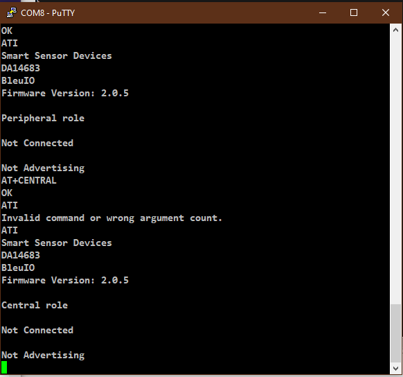
  •  Enter the ATI command to see its current config. Based on the response you’ll see it is configured as a Peripheral.
  • Enter the AT+CENTRAL command to configure the dongle as a Central device. Verify status with ATI command.

And that’s it! The dongle is good to go! It’s that simple.

Refer to the AT commands reference guide here.

Now we need to set up the example BLE code.

Setup Test Code

For our test, we’ll be using the Nordic NRF5 SDK.  This SDK contains a rich collection of examples to get you started. For this particular test, we’ll be using a slightly modified version of the BLE App Heart Rate Sensor Peripheral example (the ble_app_hrs project can be found in the examples/ble_peripheral folder in the SDK).

You need to download and install Segger Embedded Studio (SES) to try out the project.

To quickly get started, check out the example code repo on my GitHub page. To run the example project:

  1. Go to download location > bleuio_dongle_test > ses .
  2. Open bleuio_dongle_ble_test.emProject using Segger Embedded Studio.
  3. Start a debug session (this automatially compiles the code). On the menu bar go to Debug > Go.
  4. The NRF52840-DK should now be flashed with the example code.
  5. You will observe that LED 1 on the DK is flashing. This indicates it is advertising.

To verify the code is running, observe the Debug output in the Debug Terminal (in SES):

A BLE device in the peripheral role advertises itself. In this example, the device is advertising itself using the name KnightRider. We’ll be using this later.

Now that both the device and dongle are ready, let’s test out basic BLE functionality.


Basic BLE functionality Test

Finally we can perform basic BLE functionality tests. We will cover 2 very basic areas:

  • Advertising
  • Connecting (not pairing)


Advertising

From the Putty Terminal, send the AT command AT+GAPSCAN=X (where X is the scan duration in seconds). This returns a list of detected Bluetooth/BLE devices.
As you can see, KnightRider is alive and kicking:


Connecting

To connect to KnightRider, enter the command AT+GAPCONNECT, followed by the address type and device address. See AT command reference guide for details.

In a second or two, you’ll see something like this:

Conclusion

We’ve looked at how we can use the BleuIO dongle for doing basic BLE connectivity tests. It proves to be a very handy tool for developing BLE projects. With Python and Javascript libraries available at your disposal, there’s no limit to what you can do with this dongle.

I am developing a full course on the academy – where you can learn about kickstarting BLE development projects. Stay tuned.

Callbacks in Embedded C

Callbacks in Embedded C

C is a powerful language – which is both awesome and scary for obvious reasons – we’ll talk about that some other time. So what is it that makes C so powerful? One word comes to mind – Pointers! Pointers give you pretty much unlimited access and flexibility when writing programs. One exceptionally good application of pointers (specifically function pointers) is callbacks.

The general idea of callbacks can be quite confusing at first (I remember it took me a while to really grasp the concept and the many ways you can use it). So, let’s break this down, shall we?

First and foremost, don’t get intimidated by the terminology itself. A callback is just a function, like any other normal function in C.

Here’s a completely normal function – this one turns on an LED:

[et_pb_dmb_code_snippet code=”dm9pZCBsZWRfb24odWludDhfdCBwaW4pIAp7ICAgIAogICAgbnJmeF9ncGlvdGVfb3V0X3NldChwaW4pOwp9IA==” copy_button=”on” _builder_version=”4.9.10″ _module_preset=”default” custom_margin=”10px|||||” custom_padding=”0px|||||” hover_enabled=”0″ sticky_enabled=”0″]dm9pZCBsZWRfb24odWludDhfdCBwaW4pIAp7ICAgIAogICAgbnJmeF9ncGlvdGVfb3V0X3NldChwaW4pOwp9IA==[/et_pb_dmb_code_snippet]

Here’s another completely normal function – this one turns off an LED:

[et_pb_dmb_code_snippet code=”dm9pZCBsZWRfb2ZmKHVpbnQ4X3QgcGluKSAKeyAgICAKICAgIG5yZnhfZ3Bpb3RlX291dF9jbGVhcihwaW4pOyAKfQ==” copy_button=”on” _builder_version=”4.9.10″ _module_preset=”default” hover_enabled=”0″ sticky_enabled=”0″ language=”c”]dm9pZCBsZWRfb2ZmKHVpbnQ4X3QgcGluKSAKeyAgICAKICAgIG5yZnhfZ3Bpb3RlX291dF9jbGVhcihwaW4pOyAKfQ==[/et_pb_dmb_code_snippet]

These completely “normal” functions can also be callbacks. How? Keep reading.

Consider a very simple example. Let’s say you have a function that reads a temperature sensor. Whenever the sensor reads a temperature greater than room temperature (let’s say 22 degrees Celsius), something should happen with the LED. One traditional solution could be

[et_pb_dmb_code_snippet code=”IyBkZWZpbmUgU1RBTkRBUkRfUk9PTV9URU1QICAgICAyMiAKCnZvaWQgZ2VuZXJhdGVfYWxlcnQodm9pZCkKeyAgICAgCiAgLy8gUHNldWRvL2dlbmVyaWMgZnVuY3Rpb24gdG8gcmVhZCB0ZW1wZXJhdHVyZSAgIAogIGludDhfdCByb29tX3RlbXAgPSByZWFkX3RlbXBlcmF0dXJlKCk7IAogIAogIGlmKHJvb21fdGVtcCA+IFNUQU5EQVJEX1JPT01fVEVNUCkgICAgCiAgeyAgICAgICAgIAogICAgbGVkX29uKCk7ICAgCiAgfQp9″ copy_button=”on” _builder_version=”4.9.6″ _module_preset=”default”]IyBkZWZpbmUgU1RBTkRBUkRfUk9PTV9URU1QICAgICAyMiAKCnZvaWQgZ2VuZXJhdGVfYWxlcnQodm9pZCkKeyAgICAgCiAgLy8gUHNldWRvL2dlbmVyaWMgZnVuY3Rpb24gdG8gcmVhZCB0ZW1wZXJhdHVyZSAgIAogIGludDhfdCByb29tX3RlbXAgPSByZWFkX3RlbXBlcmF0dXJlKCk7IAogIAogIGlmKHJvb21fdGVtcCA+IFNUQU5EQVJEX1JPT01fVEVNUCkgICAgCiAgeyAgICAgICAgIAogICAgbGVkX29uKCk7ICAgCiAgfQp9[/et_pb_dmb_code_snippet]

Fairly straightforward, right? Here, the LED turns on if the room temperature is greater than 22 degrees. But then the question becomes: what if we wanted to turn off the LED, or blink it for a few seconds? What if we wanted to do something completely different?

Let’s look at a more flexible solution – using callbacks.

To begin using callbacks, the first thing you need to do is define a function pointer. To get started, consider the two “action” functions:

[et_pb_dmb_code_snippet code=”dm9pZCBsZWRfb24odWludDhfdCBwaW4pOyAgCnZvaWQgbGVkX29mZih1aW50OF90IHBpbik7″ copy_button=”on” _builder_version=”4.9.6″ _module_preset=”default”]dm9pZCBsZWRfb24odWludDhfdCBwaW4pOyAgCnZvaWQgbGVkX29mZih1aW50OF90IHBpbik7[/et_pb_dmb_code_snippet]

Can you see what they both have in common? They both take in parameters of type uint8_t and do not return anything. Therefore, an appropriate function pointer declaration would be:

[et_pb_dmb_code_snippet code=”dHlwZWRlZiB2b2lkICgqbGVkX2FjdGlvbikodWludDhfdCBwaW4pOyAK” copy_button=”on” _builder_version=”4.9.6″ _module_preset=”default”]dHlwZWRlZiB2b2lkICgqbGVkX2FjdGlvbikodWludDhfdCBwaW4pOyAK[/et_pb_dmb_code_snippet]

Note that it is called a “function pointer”- meaning it points to a function, not data. How do you read a function pointer declaration? Read from the middle – in this case, the pointer points to some unknown function that takes one parameter and returns nothing. The key here is understanding that we are pointing to some function; we just don’t know what it is yet.

A good rule of that thumb that I follow religiously when declaring function pointers is to use a name that is somewhat generic and encapsulates/captures a wide range of expected actions within the given context. In this case, the function pointer name led_action gives you a pretty good idea of the kind of function(s) that it points to.


Why use typedef? It simply makes the code easier to read. By using typedef, you are saying that led_action is a type – in this case, a function pointer. A little more on this later.

Now we can redefine our generate_alert function (with the mutual understanding that something needs to happen if the temperature is above 22 degrees):

[et_pb_dmb_code_snippet code=”IyBkZWZpbmUgU1RBTkRBUkRfUk9PTV9URU1QICAgICAyMiAgICAgIAoKCnZvaWQgZ2VuZXJhdGVfYWxlcnQobGVkX2FjdGlvbiBhY3Rpb24pIAp7ICAgIAogICAgQVNTRVJUKGFjdGlvbiAhPSBOVUxMKTsgICAgICAgIAogIAogICAgaW50OF90IHJvb21fdGVtcCA9IHJlYWRfdGVtcGVyYXR1cmUoKTsKICAgICAJCSAgIAogICAgaWYocm9vbV90ZW1wID4gU1RBTkRBUkRfUk9PTV9URU1QKSAgICAKICAgIHsgICAgICAgICAKICAgICAgYWN0aW9uKCk7IC8vSGVyZSB3ZSBhcmUgY2FsbGluZyBzb21ldGhpbmcgdGhhdCB3ZSBETyBOT1QgWUVUIEtOT1cgIAogICAgfQp9IA==” copy_button=”on” _builder_version=”4.9.6″ _module_preset=”default”]IyBkZWZpbmUgU1RBTkRBUkRfUk9PTV9URU1QICAgICAyMiAgICAgIAoKCnZvaWQgZ2VuZXJhdGVfYWxlcnQobGVkX2FjdGlvbiBhY3Rpb24pIAp7ICAgIAogICAgQVNTRVJUKGFjdGlvbiAhPSBOVUxMKTsgICAgICAgIAogIAogICAgaW50OF90IHJvb21fdGVtcCA9IHJlYWRfdGVtcGVyYXR1cmUoKTsKICAgICAJCSAgIAogICAgaWYocm9vbV90ZW1wID4gU1RBTkRBUkRfUk9PTV9URU1QKSAgICAKICAgIHsgICAgICAgICAKICAgICAgYWN0aW9uKCk7IC8vSGVyZSB3ZSBhcmUgY2FsbGluZyBzb21ldGhpbmcgdGhhdCB3ZSBETyBOT1QgWUVUIEtOT1cgIAogICAgfQp9IA==[/et_pb_dmb_code_snippet]

At this point, you are basically saying – if the temperature is above 22, do something. What you actually do – comes later.

The line

[et_pb_dmb_code_snippet code=”QVNTRVJUKGFjdGlvbiAhPSBOVUxMKTsgCg==” copy_button=”on” _builder_version=”4.9.6″ _module_preset=”default” custom_padding=”0px|||||”]QVNTRVJUKGFjdGlvbiAhPSBOVUxMKTsgCg==[/et_pb_dmb_code_snippet]

Is just good programming style – you are basically ensuring that the unknown function, whatever it may be, wherever it may be, actually exists, otherwise, you are in for a world of pain (aka undefined behaviour)! To put it bluntly, it’s just a good way to cover your ass.

What the ASSERT does, depends on your platform and implementation. During debugging, the program would halt on that line. In a production build, the program might reboot when it hits that assertion. You have to decide what happens. In any case, always check that the target function is defined before calling it. This will potentially save you hours of debugging. A slightly less aggressive approach could be:

[et_pb_dmb_code_snippet code=”IyBkZWZpbmUgU1RBTkRBUkRfUk9PTV9URU1QICAgICAyMiAgICAgIAoKCnZvaWQgZ2VuZXJhdGVfYWxlcnQobGVkX2FjdGlvbiBhY3Rpb24pIAp7ICAgICAgICAgIAogICAgaW50OF90IHJvb21fdGVtcCA9IHJlYWRfdGVtcGVyYXR1cmUoKTsKICAgICAJCSAgIAogICAgaWYocm9vbV90ZW1wID4gU1RBTkRBUkRfUk9PTV9URU1QKSAgICAKICAgIHsgCiAgICAgICAvLyBFeGVjdXRlIHRoZSBhY3Rpb24gaWYgaXRzIGRlZmluZWQvYXZhaWxhYmxlCiAgICAgICBpZihhY3Rpb24gIT0gTlVMTCkKICAgICAgIHsKICAgICAgICAgICBhY3Rpb24oKTsKICAgICAgIH0gICAgICAgCiAgICB9Cn0g” copy_button=”on” _builder_version=”4.9.6″ _module_preset=”default”]IyBkZWZpbmUgU1RBTkRBUkRfUk9PTV9URU1QICAgICAyMiAgICAgIAoKCnZvaWQgZ2VuZXJhdGVfYWxlcnQobGVkX2FjdGlvbiBhY3Rpb24pIAp7ICAgICAgICAgIAogICAgaW50OF90IHJvb21fdGVtcCA9IHJlYWRfdGVtcGVyYXR1cmUoKTsKICAgICAJCSAgIAogICAgaWYocm9vbV90ZW1wID4gU1RBTkRBUkRfUk9PTV9URU1QKSAgICAKICAgIHsgCiAgICAgICAvLyBFeGVjdXRlIHRoZSBhY3Rpb24gaWYgaXRzIGRlZmluZWQvYXZhaWxhYmxlCiAgICAgICBpZihhY3Rpb24gIT0gTlVMTCkKICAgICAgIHsKICAgICAgICAgICBhY3Rpb24oKTsKICAgICAgIH0gICAgICAgCiAgICB9Cn0g[/et_pb_dmb_code_snippet]

Now we are ready to call the function. If we wanted the LED to turn on, when the temperature went past 22 degrees, we would simply have to say:

[et_pb_dmb_code_snippet code=”Z2VuZXJhdGVfYWxlcnQobGVkX29uKTsg” copy_button=”on” _builder_version=”4.9.6″ _module_preset=”default”]Z2VuZXJhdGVfYWxlcnQobGVkX29uKTsg[/et_pb_dmb_code_snippet]

If we wanted the LED off, we’d say:

[et_pb_dmb_code_snippet code=”Z2VuZXJhdGVfYWxlcnQobGVkX29mZik7IA==” copy_button=”on” _builder_version=”4.9.6″ _module_preset=”default”]Z2VuZXJhdGVfYWxlcnQobGVkX29mZik7IA==[/et_pb_dmb_code_snippet]

So what have we really achieved here? We have made the generate_alert function more flexible and generic by passing a different action to it, depending on the requirement. This way, you could literally pass in any action, provided it followed the function pointer prototype. Ideally you could pass any function, but then you’d get compile warnings that the function you are passing does not match the expected prototype. Personally I tend to treat warnings as errors – helps me sleep better at night.

This is what makes a normal function a callback – by passing it as an argument to another function. Just like you would pass data to a function, you can also pass a function to another function.

A quick note on the typdef subject. If we hadn’t used typedef to declare the function pointer, then the generate_alert function prototype would look like this:

[et_pb_dmb_code_snippet code=”dm9pZCBnZW5lcmF0ZV9hbGVydCh2b2lkICgqbGVkX2FjdGlvbikodWludDhfdCkpOyA=” copy_button=”on” _builder_version=”4.9.6″ _module_preset=”default”]dm9pZCBnZW5lcmF0ZV9hbGVydCh2b2lkICgqbGVkX2FjdGlvbikodWludDhfdCkpOyA=[/et_pb_dmb_code_snippet]

I guarantee you that you’d have to take at least a second (and maybe a third) look to understand that prototype. By “typdef-ing”the declaration of the function pointer, we end up with a much nicer-to-read prototype:

[et_pb_dmb_code_snippet code=”dm9pZCBnZW5lcmF0ZV9hbGVydChsZWRfYWN0aW9uIGFjdGlvbik7IA==” copy_button=”on” _builder_version=”4.9.6″ _module_preset=”default”]dm9pZCBnZW5lcmF0ZV9hbGVydChsZWRfYWN0aW9uIGFjdGlvbik7IA==[/et_pb_dmb_code_snippet]

Ah.. that’s better!

Conclusion

Callbacks provide abstraction, flexibility, and decoupling. By using this format, we did not explicitly bind the generate_alert function to one specific LED action.

I especially love using callbacks because they allow you to design flexible, event-driven programs. When using function pointers and callbacks, remember:

  • To use function pointer names that cover the range of actions you will potentially perform in the future; makes the code easier to read.

  • To use assertions and/or exception handling techniques to verify that the intended target function exists. Always use protection; pun intended.

  • To use typedef to declare function pointers; makes your code much easier to read.

CI/CD For Firmware Development, Part II

CI/CD For Firmware Development, Part II

In Part I of this article, we looked at how to “kickstart” the CI/CD mindset during your development process. In this article, we round things off by examining vital component of this process – testing.

5. Test Automation – Static Code Analysis

Now that build scripts and pipeline scripts have been setup and running on your CI server, the stage is set. From here, you expand your pipeline and add more stages. For the next step, I’d recommend adding Static Code Analysis (SCA). Static code analysis scans your code to reveal potential vulnerabilities such as null pointer problems, buffer overflows, memory leaks, division by zero, etc. Upon completion of scanning your code, the SCA tool generates a report showing the vulnerable areas of our code, as well as the severity levels of the detected issues.
Two things to keep in mind when using SCA tools:

  • I often find that different SCA tools have their strengths and weaknesses, so I’d recommend to combine at least 2 different tools. for example, Flawfinder is very good at catching potential buffer overflow errors and format string errors, but does not consider data type issues. SPLINT on the other hand, does much deeper analysis.
  • The code analysis sometimes produces false negatives; not every reported issue is necessarily a problem. You’ll have to asses each issue in the given context.

Depending on your team ambition level (and budget), you might want to opt for open-source or proprietary solutions. Personally I don’t have a specific preference when it comes to SCA tools; I combine 2-3 different tools, and that’s more than enough.

Once again, this is a step that can be automated. Create scripts that run static code analysis and add them to your CI pipeline. If you want to be strict (and I’d recommend a reasonable level of strictness), you can set minimum severity levels that will let your pipeline fail. This will enable the team to quickly act and fix the error. For example, Flawfinder uses a scale of 0 – 5 to define vulnerability levels. You could then define your script to fail the analysis if a vulnerability of level 3 or above is detected. That should keep your team on their toes.

6. Test Automation  – Unit Testing

Unit testing requires a bit more work to setup compared to SAST. If you are a fan of TDD (Test Driven Development), then this is for you. Personally, I never really got into the TDD mindset – which essentially requires you to write tests before you write the actual code (or at least write code and tests simultaneously).

If your teams happens to be one of the few that practice TDD, I say, weldone. And if you’re looking to get into TDD, look no further than James W. Greening’s Test Driven Development for Embedded C.
You can also automate unit test runs by adding the relevant scripts to your CI pipeline. You could use the CppUTest framework to write your unit tests.

7. Test Automation  – Hardware-In-Loop (HIL) Testing

My favorite type of testing. Essentially HIL testing, at least in the context of embedded development involves executing tests on the physical embedded device itself. Conceptually, here are the key elements involved:

  • A test script – written in Python, C++ or any preferred language. The script runs on your CI slave/runner.
  • The embedded device is physically connected to the CI slave/runner. Depending on your embedded device, it may be powered via the CI slave/runner, or a separate power source. You might need to have control mechanisms (like relays, for example) that provide external stimuli to your embedded device.
  • Through the test script, commands are sent to the embedded device.
  • A bi-directional transport protocol (like UART), implemented between your script and the target embedded device, allows for the script to communicate with the embedded device, and vice versa.
  • The embedded device receives a command from the script and executes the relevant subroutines. You would have to implement a module in your embedded code which would specifically handle execution of these test commands and sending back responses via the implemented transport protocol. I’d strongly recommend you to try as much as possible to decouple this module from the rest of your application code; remember it’s only purpose is for testing, and will not be in the final release.
  • The embedded device sends a response back to the script. The script validates the response, and the next command is sent, and so on.


There are a number of test frameworks you can use for embedded HIL testing – I’d highly recommend Pytest or Robot Framework. And once more, not to sound like a broken record, automate! Add the scripts to your CI pipeline so that tests will run on every commit.

You can split your tests into groups (or suites), in such a way that quick, sanity tests will run whenever daily commits are made. Then you can configure your pipeline to run nightly, where ALL tests, which could potentially take hours, will be executed. Another way of splitting your tests is to group them by feature. The options are limitless.

If you’re visual like me, you’ll also setup a TV dashboard so you can see build and test results when you come to work in the morning, as well as monitor build and test activities during the day. I’d warn you though, coming to the office in the morning to see a dashboard where all tests have failed could be a stressful way to start your day. It’s never a great start to come in at 9 in the morning and the first thing you say is the F word.


8. Setup Release Workflow

Your release workflow will also heavily depend on your team, project requirements, and your target customers (either another team in the company or end users of your software). In any case, find a workflow that works best for you, and, you guessed it.. automate!

Automate your release workflow as much as you can. Your CI server is there to make it happen. Use it to create tags, release candidates, whatever suits you. Finally, be sure to have a versioning strategy for your software. Semantic versioning tends to work well in most cases.

Conclusion

At the very minimum, you should have the following pipeline stages running on your CI server everyday (multiple times a day):

  • Build
  • Static Code Analysis
  • Unit tests and/or HIL tests

Setting all this up is the hard part. Once the mechanisms are in place, it’s a matter of maintenance. You’ll have to do a lot of scripting to get this workflow running because every embedded project is unique; we don’t have the luxury of pulling generic tools off the shelf.

Automate as much as you can, wherever and whenever it makes sense to do so. Not everything can be automated unfortunately; do not underestimate the important of manual testing. Do not fully rely on automated tests.

In an ideal situation, you want to establish this workflow as soon as possible when you start a new project. Then it becomes a daily routine for your team. As for already existing projects, your team will have to invest considerable time, resources and effort. But trust me, it will be time well and truly spent.

In the end, it’s all worth it, and it gives you and your team peace of mind.

CI/CD For Firmware Development, Part I

CI/CD For Firmware Development, Part I

Continuous Integration / Continuous Delivery, or more popularly known as CI/CD is probably one of the biggest hot-button topics in software development. There are hundreds, if not thousands of articles on the subject. That being said, I will not dive into the specifics of CI/CD itself. Instead I will (try) to put CI/CD in the context of embedded software development.

CI/CD at its core is essentially a set of development practices which ensure that quality software is delivered (and on time). The results of a CI/CD workflow, includes, but is not limited to – a considerably reduced development cycle, quick discovery and resolution of software bugs and overall increase in software quality.

To help put the concept into the context of embedded software development, ask yourself:

  • Where is your code hosted?
  • How do you integrate code from members of your team?
  • How do you quickly ensure code quality?
  • How do you quickly verify that new code does not inadvertently introduce bugs?
  • How do you quickly ensure that new code does not break existing code/functionality?
  • How do you test your code?
  • How do you ship/release your code?

If you’re in the field, then chances are you can partially answer some of these questions. In some cases, you’re probably scratching your head, or even better, daydreaming about how great it would be to be able to do those things. If you fit in any of these response groups, trust me, you’re not alone.

Embedded software development is fun (or at least it can be under the right conditions), but more importantly, it’s hard – and that’s an understatement. Being a successful embedded software developer requires a certain mindset, and I believe that adopting CI/CD principles will go a long way – both for you and your team.

In the rest of this article, we’ll answer these questions by exploring 8 concrete steps to establishing a decent CI/CD flow for your project/team.


1. Version Control

Version control (VC) ensures that you have a full history of file changes in your project. Here, you do 3 things:

  • Choose a VC tool. There are a number of version control tools, the most popular ones being Git, Subversion and CVS.
  • When you’ve chosen your desired VC tool, the next step is to choose a hosting service. Here you have quite a lot of options – GitHub, GitLab, Bitbucket, just to name a few.
  • Decide whether you want to host the code on the vendor’s cloud or on your own enterprise systems. Most (if not all) vendors give you the option of hosting your code on your own servers or on the cloud.

This might seem like a no-brainer, but you’ll be surprised to know there are still a lot of developers and teams that do not use VC. Come to think of it, I can’t possibly imagine how developers managed tons of code before version control was invented. It must have been a nightmare.


2. Develop Team Workflow And Branching Strategy

Team workflows and branching strategies vary, depending on the team and complexity of the project. In any case, I strongly believe these core workflows and strategies should be common to every team:


  • Have an issue tracking system. Jira and ClickUp are some of my personal favorites.
  • Each and every issue/task MUST be implemented on its own branch.
  • For traceability, link issues to branches. In most cases, this already happens as a result of integration between your issue tracking solution and version control system. For example, consider Jira and Bitbucket. If you created an issue in Jira, you can create a Bitbucket branch with a single click. By default, the branch would be named after the issue.
  • Code reviews MUST be conducted before merging branches. In the Git world, this is known as a “pull request”. Ensure that direct commits/merges to the master branch are disabled! This can easily be enforced using the administrator settings in your repository tool (GitLab/GitHub/Bitbucket, etc).
  • Teams should decide and enforce the criteria for merging branches to the “master” branch (passing tests, code/test coverage). It is important the team exercises discipline, otherwise, it’s a disaster waiting to happen!

3. Setup CI/CD Server

There are many options, however my personal favorites in this category are Jenkins and GitLab, particularly because they are suitable for embedded development. They allow you to define physical machines (Jenkins calls them Slaves and Nodes, GitLab calls them Runners) where you can install tools to be used for compiling your code and executing hardware-in-loop automated tests. GitHub has also recently (at the time of writing this article) also introduced Runners, but the implementation is still fairly in its early stages.

Set up the master instance (either onsite or cloud), and then set up physical machines (nodes/runners). Ideally you can set up as many nodes/runners as possible. This would allow you to distribute build and test jobs. This would be especially beneficial in a scenario where you’re working with a fairly large/complex project and there’s a lot of tests to be executed. Ensure that tools installed on all machines are the same version.


4. Build Automation

As soon as your CI/CD server is up and running, the next step is to implement build scripts and integrate with your CI/CD server:

  • Define build scripts (.sh or .bat) that compile your firmware. Ideally you create this script on your own development machine first and ensure that you can use this script to compile your application from the command prompt. The goal is to duplicate your development environment on your server. For example, if you use Segger Embedded Studio (SES) to write and build your code, then you should install the same tool (and same version) on your slave/runner. SES comes with emBuild, a utility that lets you compile your code from command-line. Most vendors these days have command-line utilities bundled with their software. Alternatively, if you are using the CMake system, then be sure to install the same on your slave/runner.
  • Define pipeline scripts – these are scripts used by your CI/CD server to build code, run tests, deploy images, etc. Pipelines are split into stages. A stage performs a concrete action, such as building your code, or running unit tests. In most cases, building your code is the very first step in the pipeline. In Jenkins, the pipeline configuration is defined in a so-called JenkinsFile, and as for GitLab, you create a .gitlab-ci.yml file which defines the pipeline configuration.
  • Automate! Configure your CI/CD server to automatically build whenever commits are made to branches. In GitLab this happens automatically; as for Jenkins, you need a bit of setup to get this to work.


At this point, we’ve established basic version control, workflows and build automation.
In Part II of this article, we’ll examine the testing aspects of CI/CD.


This website uses cookies. By continuing to use this site, you accept our use of cookies.